

Comprehensive Analysis of Hydraulic Systems
1、Definition hydraulic system
A hydraulic system, fully known as a hydraulic transmission system, refers to a system that uses liquid (typically hydraulic oil) as the working medium to transmit power and control mechanical motion through the pressure energy of the liquid. Hydraulic system uses the principle of pressure applied to a confined fluid is transmitted undiminished in all directions throughout the fluid and to the container walls. Inorder to convert mechanical energy into hydraulic energy, and then back into mechanical energy, thereby performing external work.
Hydraulic systems can be divided into two major categories: hydraulic transmission systems (primarily for transmitting power and motion) and hydraulic control systems (to ensure system output meets specific performance requirements). The term "hydraulic system" generally refers to the former.
2、Application Fields of Hydraulic Systems
Hydraulic systems are widely used across various industries due to their advantages such as high output force and high power density:
-
Construction Machinery: Boom extension/retraction and bucket opening/closing in excavators; various actuations in loaders, bulldozers, and cranes.
-
Machine Tools and Manufacturing Equipment: Various metal-cutting machine tools, injection molding equipment, hydraulic presses, waste compactors, etc.
-
Transportation: Automotive brake systems, aircraft landing gear and flight control surface actuation, ship steering systems.
-
Metallurgy and Mining: Rolling mills, mining machinery, and other heavy-load equipment.
-
Testing and Measurement Equipment: Various material testing machines, fatigue test benches, etc.
From the perspective of application scenarios, they can be divided into stationary applications (e.g., production equipment in factory workshops) and mobile applications (e.g., mobile machinery)
3、How a Hydraulic System Works (Working Principle)
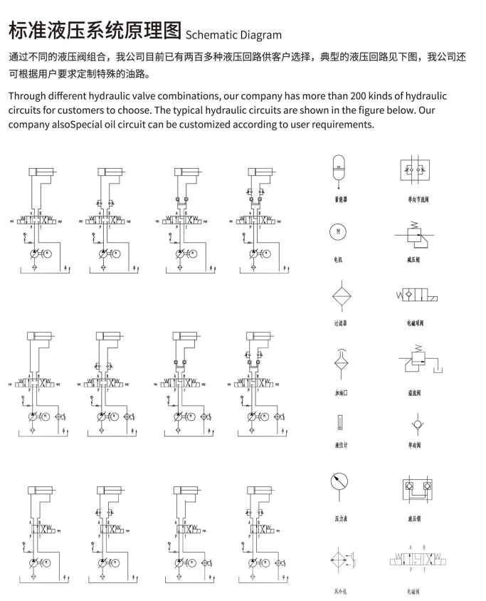
The working process of a hydraulic system
is a closed-loop process of energy conversion and transmission:
Power Input Stage: The prime mover (electric motor or engine) drives the hydraulic pump to rotate, and the pump converts mechanical energy into fluid pressure energy. The pump draws low-pressure oil from the reservoir and converts it into high-pressure oil output to the system.Control and Regulation Stage: High-pressure oil flows through various control valves via pipelines. According to system commands, the control valves precisely regulate the pressure, flow rate, and flow direction of the oil, distributing the oil to designated actuating components as required.Power Output Stage: The regulated oil enters the actuating components. If the actuating component is a hydraulic cylinder, it pushes the piston to perform linear reciprocating motion; if it is a hydraulic motor, it drives the rotor to perform continuous rotary motion. The actuating components convert pressure energy back into mechanical energy to drive the load to perform work.Return Oil and Circulation Stage: The low-pressure oil after completing work returns to the reservoir through the return line. After filtration and cooling, it is drawn again by the hydraulic pump to begin the next cycle.
4、Advantages of Hydraulic Systems
Compared with mechanical transmission and electrical transmission, hydraulic transmission offers the following significant advantages:
-
High Output Force/Torque: Can output extremely large thrust or torque with a relatively small volume, especially suitable for low-speed and heavy-load conditions.
-
High Power Density: Under the same power rating, hydraulic devices are smaller, lighter, and more compact in structure.
-
Wide Stepless Speed Regulation Range: Can achieve a wide range of stepless speed regulation with smooth adjustment, adjustable during operation.
-
Overload Protection and Self-lubrication: The system has built-in overload protection (achieved through relief valves), ensuring safety and reliability. Meanwhile, the hydraulic oil serves as the working medium and also provides lubrication for moving parts, extending service life.
-
Flexible Layout: Hydraulic components can be connected via pipes or manifold blocks, offering flexible installation and the ability to form complex systems.
-
Easy Automation: Simple operation, easy to combine with electronic control to achieve complex automatic cycles and remote control.
Major disadvantages include: relatively low efficiency (typically below 80%), sensitivity to temperature changes (unsuitable for extremely high or low temperature operations), sensitivity to contamination (about 70% of failures are caused by contamination), leakage risks, and relatively difficult fault diagnosis.
5、Maintenance of Hydraulic Systems
-
Maintain Oil Cleanliness: Regularly inspect oil filters and replace filter elements according to specifications; prevent impurities from entering the system during oil filling or maintenance.
-
Control Oil Temperature: Maintain appropriate working oil temperature (typically 30~60°C) to avoid oil oxidation caused by excessive temperature.
-
Regular Inspection and Oil Change: Periodically test oil performance indicators (viscosity, water content, acid value, etc.), and change hydraulic oil at intervals as required by equipment specifications.
-
System Inspection: During operation, monitor noise, observe pressure gauge readings, check for pipeline leakage, and address any abnormalities promptly.
-
Proper Installation and Commissioning: For new systems or after major overhauls, perform installation, cleaning, commissioning, and trial operation according to procedures.
6、Basic Components of a Hydraulic System (Composition)
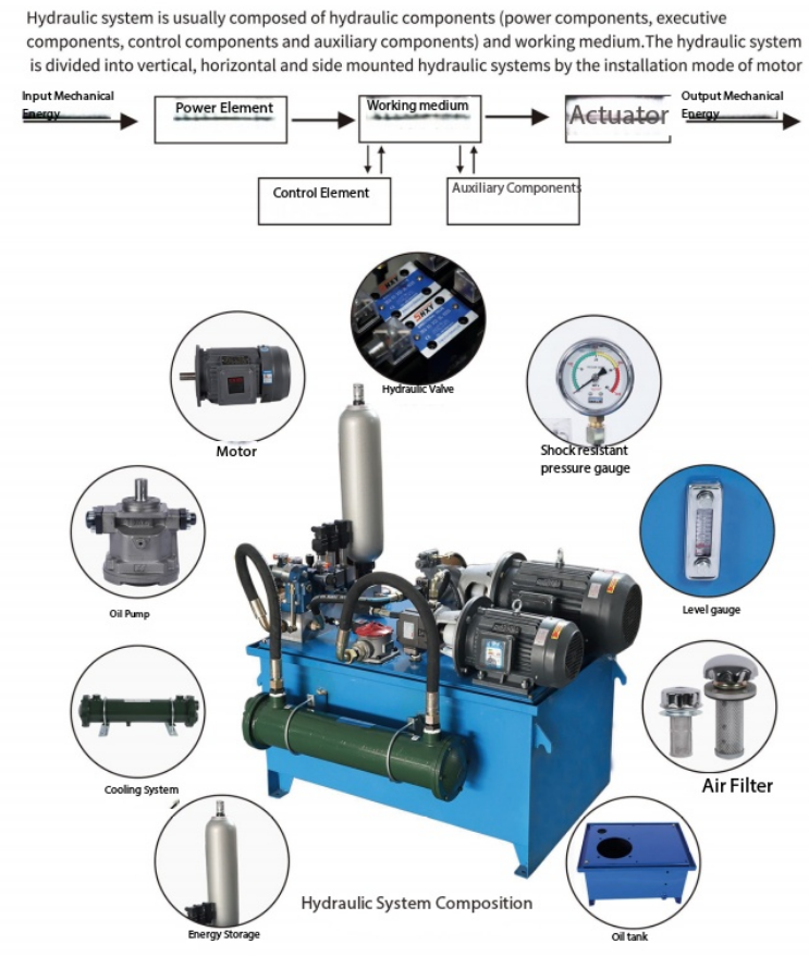
A complete hydraulic system consists of five basic components:
Power Component — Hydraulic Pump
-
Function: Converts the mechanical energy of the prime mover into fluid pressure energy, serving as the "heart" of the entire system.
-
Common Types: Gear pump, vane pump, piston pump, screw pump, etc.
Actuating Components — Hydraulic Cylinders and Hydraulic Motors
-
Function: Convert fluid pressure energy into mechanical energy to drive the load to perform work.
-
Hydraulic Cylinder: Achieves linear reciprocating motion.
-
Hydraulic Motor: Achieves continuous rotary motion.
Control Components — Hydraulic Valves
-
Function: Control and regulate the pressure, flow rate, and flow direction of the fluid.
-
Classification:
-
Pressure Control Valves: Relief valve (safety valve), pressure reducing valve, sequence valve, pressure switch, etc.
-
Flow Control Valves: Throttle valve, flow control valve with pressure compensation, flow divider/combiner, etc.
-
Directional Control Valves: Check valve, directional valve, pilot-operated check valve, etc.
-
Auxiliary Components
-
Function: Provide necessary support and auxiliary functions for normal system operation.
-
Mainly Includes: Reservoir, oil filter, cooler, heater, accumulator, pipes and fittings, seals, pressure gauge, oil level gauge, oil thermometer, etc.
Working Medium — Hydraulic Oil
-
Function: The working medium for energy transmission.
-
Types: Various mineral oils, emulsions, synthetic hydraulic oils, etc.
7、Assembly Relationship of Components in a Hydraulic System
Assembly Sequence and Logic:
- Power Source End: Prime mover → Hydraulic pump (power component) → The pump draws oil from the reservoir (auxiliary component) through the suction line and outputs high-pressure oil.
- Control End: High-pressure oil passes through the valve manifold (pressure valves, directional valves, and flow valves combined according to circuit design). This part is the core of system design, determining the system's motion logic and performance.
- Actuating End: The oil regulated by the valve manifold is delivered through pipelines (auxiliary components) to the hydraulic cylinder or hydraulic motor (actuating components) to drive the load.
- Return Oil End: The low-pressure oil discharged by the actuating components returns to the reservoir (auxiliary component) through the return line after passing through the oil filter (auxiliary component), completing the cycle.
- Auxiliary Circuits: The accumulator (auxiliary component) can serve as an auxiliary power source or absorb pulsations; coolers/heaters (auxiliary components) are used for oil temperature control; pressure gauges (auxiliary components) are used for condition monitoring.
8、About Ruiheng Right Pneumatic
RIH is a manufacturer with over 20 years of experience in producing pneumatic and fitting products, as well as solenoid valves, pipe fittings in various materials, valves, tubes, and more. We hold CE certification and invention patents, and we also support custom color and size options. Please feel free to contact us for more information, product catalogs, or to place an order–you can download these materials directly from our website or send us an email.amy@cnrih.com OR rita@rihpneumatic.com